40 Results
View results:
Sort by:
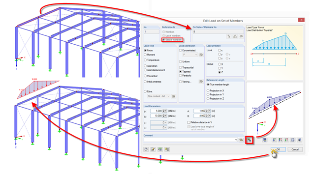
RFEM and RSTAB provide a helpful preview to check the input of member and line loads in the dialog box.

The dialog box for editing load or result combinations is a non-modal dialog box. This means that after you open this dialog box, you can edit the combinations outside the dialog box as well. For manually defining or editing a combination, a separate dialog box can be opened parallel to the "Edit load cases and combinations" dialog box.

In CRANEWAY, the action of a rail as "statically effective" or "statically ineffective" is defined under "Rail‑Flange Connection" in the Details dialog box. This setting controls the calculation of the load introduction length according to EN 1993-6, Tab. 5.1.

In RF‑TENDON and RF‑TENDON Design, you can review and adjust the code‑dependent factors, calculation parameters, and calculation methods using the "Code" button. You can display the settings and adjustment options according to a chapter of a code, selecting the "Grouping" option in the dialog box.
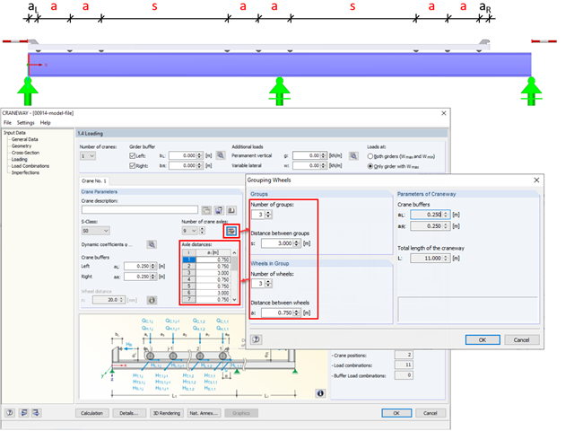
In CRANEWAY, the "Grouping Wheels" dialog box allows you to generate efficient groups with equal intervals.
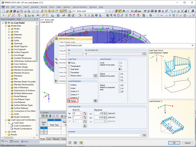
The "Radial" load distribution dialog box is available in RFEM for the quick generation of radial surface loads.
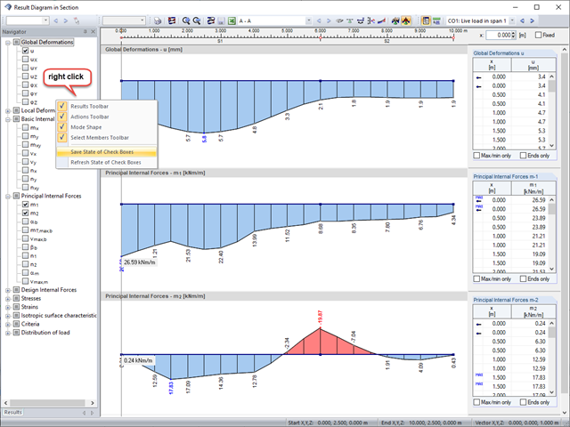
Sections are an excellent way to display and evaluate results clearly. In the RFEM and RSTAB section dialog boxes, you can display several result types at the same time.

For the design of concrete surfaces, the rib component of the internal forces can be neglected for the ULS calculation and for the analytical method of the SLS calculation, because this component is already considered in the member design. To do this, select the check box in the "Details" dialog box. If no rib was defined, this function is not available.

In the "Edit Load Cases and Combinations" dialog box, you can combine different load cases in one load combination under the "Load Combinations" tab.

You can use the elastic support option to avoid singularities due to a fixed nodal support in RFEM. This can be defined directly in the dialog box of the nodal support as a column in Z. It is necessary to take into account the geometry of the column, the material, and the support conditions. Here, we want to look at the option of modeling the column as a surface foundation.
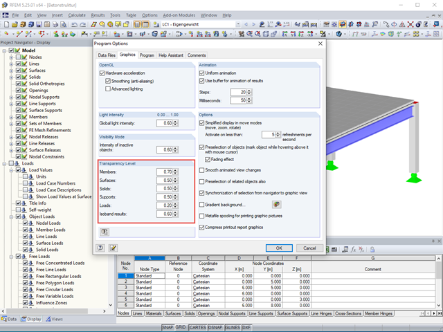
The transparency intensity of various graphic elements in the Solid Transparent Display Mode can be edited individually in the Program Options dialog box under the Graphic tab to improve the overview.
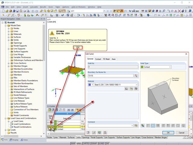
By double‑clicking the element numbers (first column) of the table, the corresponding dialog box appears.

In the RF-/FOUNDATION Pro add-on module, you can select the automatic dimensioning of the foundation plate geometry. In the dialog box for the design parameters of the foundation plate, you can, for example, specify the increment for the increase of the base area and the foundation plate thickness. You can also automatically increase the covering for a stabilizing effect of the geotechnical designs.
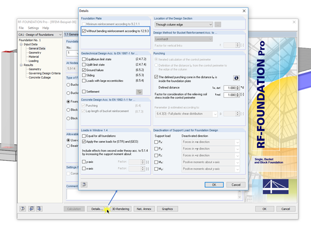
In RF-/FOUNDATION Pro, you can also calculate unreinforced foundation plates according to Section 12.9.3 of EN 1992-1-1 [1]. To do this, select the "Without bending reinforcement according to 12.9.3" check box in the "Foundation Plate" section of the "Details" dialog box.
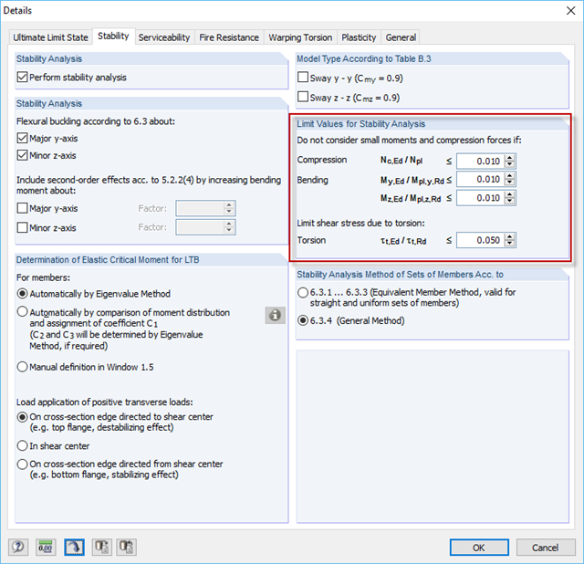
As of the program version X.11, the filter options of small compression forces or moments for stability analysis in RF‑/STEEL EC3 have been revised. The revision of these filter options in the "Stability" tab of the "Details" dialog box allows you to work in the module transparently, since they are now independent of the design.
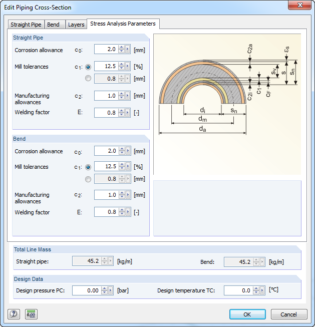
For stress calculations, some standards use the "wall thickness analysis". We get the wall thickness by subtracting corrosion, abrasion allowance, manufacturing allowances (threading, grooving, and so on), and mill tolerances from the nominal wall thickness. All necessary values can be entered in the "Piping Cross‑Section" dialog box, "Stress Analysis Parameters" tab.
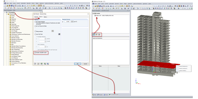
RFEM and RSTAB provide the option to "Enable CAD/BIM model" in the model's General Data dialog box, "Options" tab. In addition to creating a model as usual, this CAD/BIM model allows you to import, organize, and transform IFC, STEP, and IGES files.
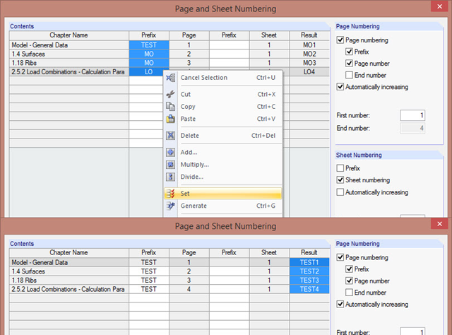
The "Page and Sheet Numbering" dialog box allows you to add a prefix to page and sheet numbering. It can be an abbreviation that specifies by chapter all model data in the numbering (for example, with "MO").
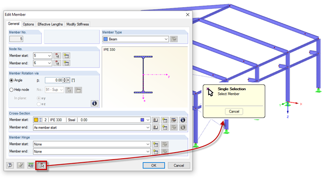
Member properties can be imported from the previously defined member in the "New Members" and "Edit Member" dialog boxes. To do this, click the [Select member and import its properties to the dialog box] button, then select the respective member.
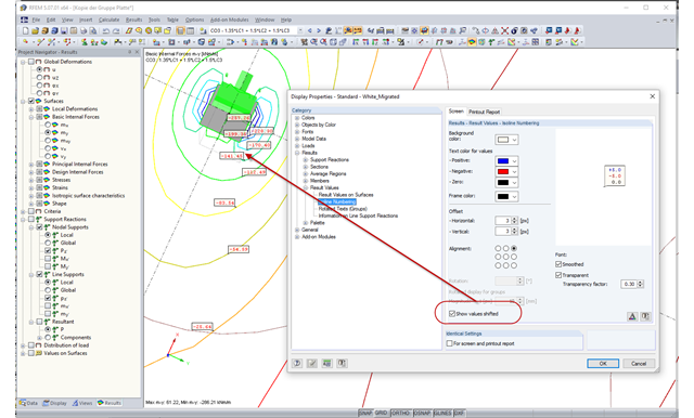
In the case of very small distances between isolines, the labels often overlap, which makes the result documentation difficult. As of RFEM version 5.06, you can select a shifted arrangement of the isoline labels in the Display Properties dialog box. By selecting the "Show values shifted" option, you can easily avoid overlapping the result values in many cases.

As in RFEM, load combinations can be generated automatically in RF‑PIPING. This feature is activated by default and creates the recommended load and result combinations for piping design. It is necessary to assign the relevant action category to load cases in order to generate the correct combinations. To do this, new action categories have been implemented specifically for loads on piping.
Pressure temperature conditions are generated as the sets of the first (second, third, and so on) load case of the "Pressure" category and the first (second, third, and so on) load case of the "Temperature" category. The default setting can be reviewed or adjusted in the "Grouping of Thermal and Internal Pressure Load Cases for Operating Combinations" dialog box. You can access this dialog box by clicking the corresponding button in the "Piping Load Combinations" tab of the "Load Cases and Combinations" dialog box. This dialog box is automatically offered to check your entries in the case of any change of the load case from the "Pressure" or "Temperature" category.
Pressure temperature conditions are generated as the sets of the first (second, third, and so on) load case of the "Pressure" category and the first (second, third, and so on) load case of the "Temperature" category. The default setting can be reviewed or adjusted in the "Grouping of Thermal and Internal Pressure Load Cases for Operating Combinations" dialog box. You can access this dialog box by clicking the corresponding button in the "Piping Load Combinations" tab of the "Load Cases and Combinations" dialog box. This dialog box is automatically offered to check your entries in the case of any change of the load case from the "Pressure" or "Temperature" category.
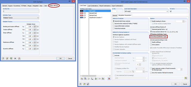
In the "Edit Surface" dialog box, there is a new tab titled "Modify Stiffness" for the "Standard" and "Without Tension" surface types. Here, you can modify the elements of a stiffness matrix by defining the factors in the same way as in the case of orthotropic surfaces.
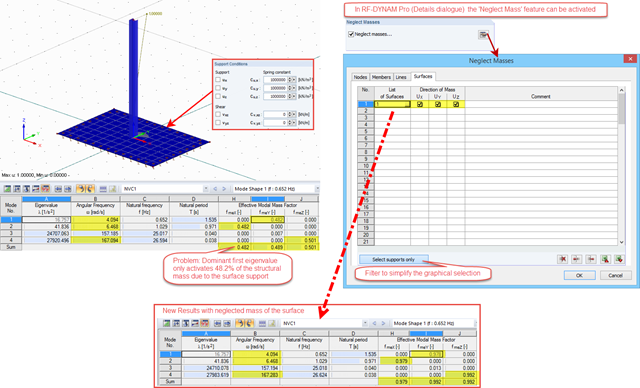
As of the version 5.06.1103, masses of nodes, lines, members, and surfaces can be neglected in RF‑DYNAM Pro. The setting to activate this feature can be found in the Details dialog box; the neglected masses are valid for all defined mass cases.
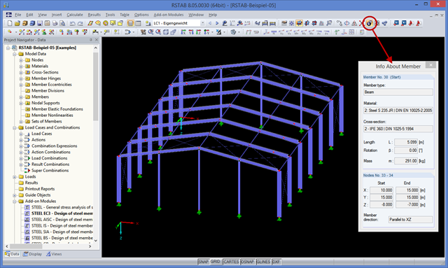
You may already be familiar with the "Center of Gravity and Info" function, which can be accessed using the shortcut menu of any element. If you want to display this information on several elements consecutively, you have to close the dialog box and open the shortcut menu of the next element over and over again.
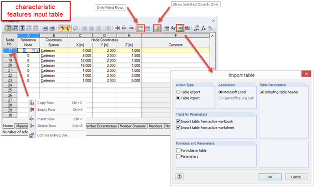
RFEM and RSTAB are programs where graphical input prevails. All data can be entered using dialog boxes, and the structure of the Project Navigator is optimized for input using the mouse. Nevertheless, you can always speed up the tabular input to reach your goal immediately.
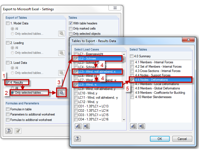
RFEM and RSTAB provide the export interface ("File" → "Export") to export model and load data, as well as results, to Excel or in a CSV file in one step. You can select the tables to be exported in the "Export Tables" section. The "Only selected tables" option allows you to export only a specific selection of tables. Use the [Select Load Cases and Tables for Export] button to open the corresponding dialog box.
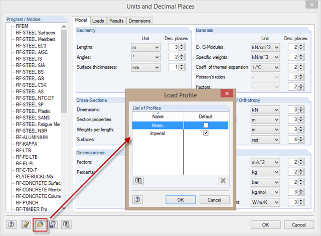
When changing the units from the metric to the imperial measurement system, it is not necessary to change all the units individually. To do this, corresponding unit profiles are available in the "Units and Decimal Places" dialog box, which you can activate as shown in the picture.
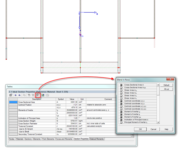
The result window of the cross-section properties can be adjusted individually using the [Filter] button in the table menu bar. You can then activate or deactivate the individual cross-section parameters in the dialog box.
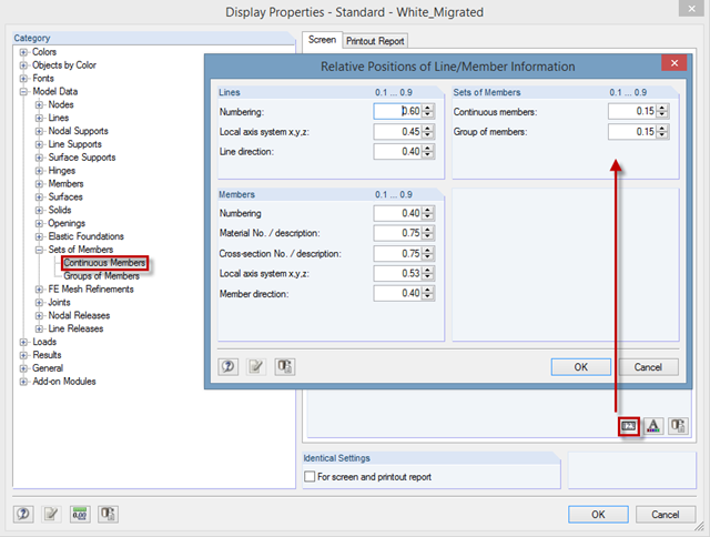
In RFEM and RSTAB, you can arrange the labeling of lines, members, and sets of members in a user‑defined way. To do this, open the dialog box in "Display Properties", where you can define the position of the information about the relative distance from the member start.
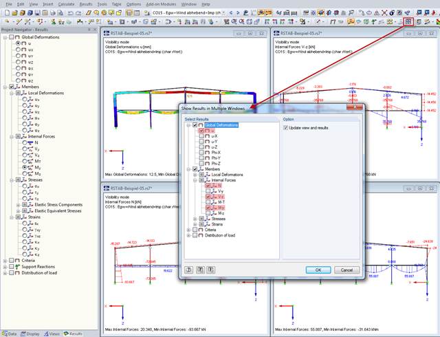
In order to show various results (deformations, internal forces) in multiple windows quickly, you can use the "Arrange Result Windows" function ("Results" menu). A dialog box appears where you can select the relevant results to be displayed.